This article provides a step-by-step explanation to how I created Universal Rayhatcher output #310, "Contact". The article assumes you have some familiarity with signed distance functions (SDFs) in general and with the specific way of writing them in the Universal Rayhatcher. If all of this is new to you, I encourage you to first read this introductory article by Ethspresso and then this prior article by me that introduces several of the techniques we'll be using again.
To follow along, you'll have to use the rayhatching development environment and set the minter address to my address. I've done this for you at this link. You'll also have to set the title seed to "Contact" and set the background to "none". I would also recommend to set the maximum marching distance to a higher value than the default. Let's set it to 150. And we'll set the line width to 0.35 to speed up rendering.
Terrain
The first thing we'll draw is terrain. In fact, let's start with completely flat terrain, where the SDF is simply the y coordinate (y measures the distance from a surface located at y = 0). We will assign this to a variable g (for ground) and then return the value of g.
g=y,
g
Ok, not that exciting. How do we create undulations? We can simply add some noise that depends on the location of the x and the z coordinates, like so:
h=nz(x,0,z,.1,2),
g=y-8*h,
g
Because we have used only two octaves of noise (specified by the parameter 2 in the argument to the nz() function), the landscape is rather smooth. We could give it more features by using more octaves, but that won't be necessary once we add all the other elements of the drawing. However, a simple way to make the terrain a bit more exciting is to exponentiate the noise value, which will create sharper peaks and broader valleys.
h=exp(-1.1*nz(x,0,z,.1,2)),
g=y-8*h,
g
So far so good, but I want the exposed ground to look like grass. A cheap way to get this effect is to just add some high-frequency noise to the landscape.
h=exp(-1.1*nz(x,0,z,.1,2)),
g=y-8*h+.1*nz(x,y,z,10,1),
g
Trees
Next we'll add trees. We can generate cheap trees using the tricks described by Inigo Quilez in the video "Painting a landscape with maths." It's a great video. Check it out.
Back to trees. In brief, each tree is an elongated ellipsoid with some noise thrown on top. So how do we generate an ellipsoid? It's actually quite tricky, but fortunately Inigo Quilez has developed a relatively simple formula that, while not exact, performs well enough in practice. We'll use a simplified version here, which has only two semi-axes that can be chosen independently, along the x and the y direction. The semi-axis along the z direction is simply the same as the one along the x direction. That's good enough for this particular drawing.
Because we'll be using ellipsoids several times in the final formula, it's a good idea to define a separate function for it. Let's call that function E(). Here you can see how it works:
E=(x,y,z,a,b)=>L(x/a,y/b,z/a)*(L(x/a,y/b,z/a)-1)/L(x/a/a,y/b/b,z/a/a);
E(x,y,z,3,15)
It does already look a bit like a tree, right? Let's add a bit of noise to complete the effect. We'll also store the SDF for the tree in a variable tr, which will help us keep track of different elements of the drawing once things become more complex.
E=(x,y,z,a,b)=>L(x/a,y/b,z/a)*(L(x/a,y/b,z/a)-1)/L(x/a/a,y/b/b,z/a/a);
tr=E(x,y,z,3,15)+.3*nz(x,y,z,1.3,1),
tr
Ok, now we need to plant the trees onto our landscape. First, let's do the standard modulo trick to replicate the tree many times. We're using a grid of size 1 by 1, and therefore have to scale down the ellipsoid so it fits into the grid. We're also adding a bit of random noise to the position of each tree (via the ri() function), so the trees don't form perfectly straight lines.
E=(x,y,z,a,b)=>L(x/a,y/b,z/a)*(L(x/a,y/b,z/a)-1)/L(x/a/a,y/b/b,z/a/a);
@xz{$m=mod($,1)-.5,$i=Z($),}
xm+=.2*ri(xi,0,zi),zm+=.2*ri(xi,5,zi),
tr=E(xm,y,zm,.2,1)+.02*nz(x,y,z,20,1),
tr
To combine the trees with the landscape, we adjust the y coordinate of each tree by the height of the landscape at the tree's location.
E=(x,y,z,a,b)=>L(x/a,y/b,z/a)*(L(x/a,y/b,z/a)-1)/L(x/a/a,y/b/b,z/a/a);
h=exp(-1.1*nz(x,0,z,.1,2)),
@xz{$m=mod($,1)-.5,$i=Z($),}
xm+=.2*ri(xi,0,zi),zm+=.2*ri(xi,5,zi),
tr=E(xm,y-8*h-.2,zm,.2,1)+.02*nz(x,y,z,20,1),
g=y-8*h+.1*nz(x,y,z,10,1),
U(g,tr)
This tree-covered landscape needs two modifications to look more realistic. First, we need to randomly remove some trees to hide the regular grid. Second, one tree per cell leaves rather large gaps between trees that might be appropriate for an orchard or designed garden but don't look like a natural landscape. We'll address both issues in turn.
First let's look into removing trees. If we just removed trees based on a coin flip, the resulting tree distribution would still look too regular. Instead, we need to remove trees based on a noise value, so that we end up with some areas where trees clump together and other areas where trees are more sparse. In addition, though, we should also remove trees based on a coin flip, so that even in the areas of high tree density we don't just get a regular grid. We can do this via a two-step process. Let's discuss them in reverse order. The second step will be a coin flip, which will look something like this: ri(xi,9,zi)<rc, where rc is the random cutoff we're using to determine whether or not to draw a tree, and 9 is an arbitrary number to ensure the random value differs from previous uses of ri(). The first step uses the noise function nz() to pick our random cutoff, depending on whether we're in the forest or in a clearing: rc=nz(x,5,z,.1,2)<0?0:-.4.
Integrating these ideas into the scene gives us the following:
E=(x,y,z,a,b)=>L(x/a,y/b,z/a)*(L(x/a,y/b,z/a)-1)/L(x/a/a,y/b/b,z/a/a);
h=exp(-1.1*nz(x,0,z,.1,2)),
@xz{$m=mod($,1)-.5,$i=Z($),}
xm+=.2*ri(xi,0,zi),zm+=.2*ri(xi,5,zi),
rc=nz(x,5,z,.1,2)<0?0:-.4,
tr=ri(xi,9,zi)<rc?E(xm,y-8*h-.2,zm,.2,1)+.02*nz(x,y,z,20,1):1000,
g=y-8*h+.1*nz(x,y,z,10,1),
U(g,tr)
The value 1000 is simply a very large distance that ensures no tree will be drawn when the random number is above the cutoff value.
Now let's make the trees denser. The idea is rather simple, but it requires a bit of code. Instead of drawing one tree per unit cell, we can just repeat the process four times with shifted coordinates so that we in effect draw four trees per unit cell.
E=(x,y,z,a,b)=>L(x/a,y/b,z/a)*(L(x/a,y/b,z/a)-1)/L(x/a/a,y/b/b,z/a/a);
tr=1000,xs=zs=0,
h=exp(-1.1*nz(x,0,z,.1,2)),
@2{i=$,xs+=i*.5,@2{j=$,zs+=i*.5,o=i+2*j,
@xz{$m=mod($+$s,1)-.5,$i=Z($+$s),}
xm+=.2*ri(xi,o,zi),zm+=.2*ri(xi,o+5,zi),
rc=nz(x,5,z,.1,2)<0?0:-.4,
t=ri(xi,o+9,zi)<rc?E(xm,y-8*h-.2,zm,.2,1)+.02*nz(x,y,z,20,1):1000,
tr=U(tr,t),
}}
g=y-8*h+.1*nz(x,y,z,10,1),
U(g,tr)
We've added a number of new variables here. Let's go through them one by one. First, i and j are the loop variables, and they each take on the values 0 and 1. We'll loop twice in the x direction and twice in the z direction to obtain a maximum of four trees per cell. Next, xs and zs are the relative shifts in x and z, and they take on the values 0 or 0.5. Then we have o, which is a simple random-number offset to ensure all random numbers are different for each iteration of the loops. Finally, because we have to combine all the trees together, we now first store the distance to the nearest tree in a variable t and then combine it with all other trees via tr=U(tr,t).
Modeling the UFO
The main body of the UFO consists of two ellipsoids, a slightly squished one in the center and a very squished one to create the outer ring. The UFO is relatively small, so we'll have to reduce the cam dist multiplier temporarily so we can look at it in detail while modeling. I'm now using a cam dist multiplier of 1.5.
E=(x,y,z,a,b)=>L(x/a,y/b,z/a)*(L(x/a,y/b,z/a)-1)/L(x/a/a,y/b/b,z/a/a);
uf=U(E(x,y,z,5,.5),E(x,y,z,3,2)),
uf
Now let's add a ring of knobs. To get circular symmetry it's generally best to go into polar coordinates, which we calculate as:
Here, r is the distance from the center and θ is the angle. We can then use the modulo trick in angular space to repeat an object along the circle. Before applying the modulo operator, we multiply the angle with 18/(2π) = 2.86 to obtain 18 repetitions. Finally, we place a little sphere into this transformed coordinate system.
E=(x,y,z,a,b)=>L(x/a,y/b,z/a)*(L(x/a,y/b,z/a)-1)/L(x/a/a,y/b/b,z/a/a);
r=L(x,z),th=mod(2.86*atan2(z,x),1)-.5,
uf=U(E(x,y,z,5,.5),E(x,y,z,3,2),L(r-4,th,y-.3)-.2)
Note that even though we have used the formula for a sphere, L(r-4,th,y-.3)-.2), because r and th don't define a Cartesian coordinate system the resulting object is not actually a sphere, but instead closer to a distorted ellipsoid. This doesn't matter though. The result we get is good enough. (But try to make the spheres larger or increase the radius of the ring and you'll see what I mean.)
The final step will be to combine the UFO with the landscape. But right now the UFO sits at the center of the coordinate system and is oriented completely horizontally. We'll want to move it up and also rotate a bit. We do this by translating and rotating the local coordinate system in which the UFO is drawn, using the rot() function for rotation and subtracting a constant from y before rotation to achieve translation. The numbers 0.94 and 0.34 in the rot() function are the cosine and the sine of 20 degrees, respectively.
E=(x,y,z,a,b)=>L(x/a,y/b,z/a)*(L(x/a,y/b,z/a)-1)/L(x/a/a,y/b/b,z/a/a);
[y,x]=rot(y-4,x,.94,.34),
r=L(x,z),th=mod(2.86*atan2(z,x),1)-.5,
uf=U(E(x,y,z,5,.5),E(x,y,z,3,2),L(r-4,th,y-.3)-.2)
Framing and final tweaks
Now we can put everything together. You'll have to set the cam dist multiplier back to 5 to get the correct framing for this scene. In the final combined code, the code for the UFO has to come last, since we're transforming the coordinate system. Alternatively we could have used different variable names to keep track of the UFO coordinates, such as [b,a]=rot(y-4,x,.94,.34), but this wasn't necessary here.
E=(x,y,z,a,b)=>L(x/a,y/b,z/a)*(L(x/a,y/b,z/a)-1)/L(x/a/a,y/b/b,z/a/a);
tr=1000,xs=zs=0,
h=exp(-1.1*nz(x,0,z,.1,2)),
@2{i=$,xs+=i*.5,@2{j=$,zs+=i*.5,o=i+2*j,
@xz{$m=mod($+$s,1)-.5,$i=Z($+$s),}
xm+=.2*ri(xi,o,zi),zm+=.2*ri(xi,o+5,zi),
rc=nz(x,5,z,.1,2)<0?0:-.4,
t=ri(xi,o+9,zi)<rc?E(xm,y-8*h-.2,zm,.2,1)+.02*nz(x,y,z,20,1):1000,
tr=U(tr,t),
}}
g=y-8*h+.1*nz(x,y,z,10,1),
[y,x]=rot(y-17,x,.94,.34),
r=L(x,z),th=mod(2.86*atan2(z,x),1)-.5,
uf=U(E(x,y,z,5,.5),E(x,y,z,3,2),L(r-4,th,y-.3)-.2),
U(g,tr,uf)
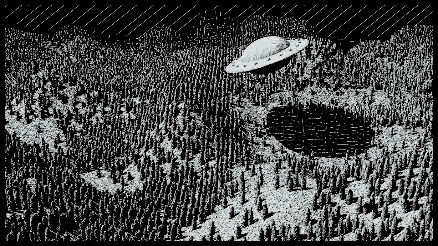
This is the final SDF, and it looks fine, but arguably it's not nearly as dramatic as the published piece. Framing and color play a huge role in the emotions an image evokes. For the UFO scene in particular, I like to invert the colors, as that to me creates the impression of night time. Let's use #010101ff for the background and #dfe6e5ff for the foreground. Let's also zoom in a bit by setting the cam zoom to 2.2. Finally, whenever we invert colors we have to adjust the shadows and mist shade parameters. We will set them to 0.47 and 0.17, respectively.
This is a nice night-time render of the landscape, but the problem is that now the UFO is gone. One difficulty with the Universal Rayhatcher project is that we don't have detailed control over camera and lighting, we're just dealt a set of cards for a given title seed and need to make the best of it. So what I commonly do is add or subtract some constants from x, y, and z at the very end to move the scene exactly into frame. Here, x+=5,y+=10,z+=10 does the trick, so this is the actual final SDF:
E=(x,y,z,a,b)=>L(x/a,y/b,z/a)*(L(x/a,y/b,z/a)-1)/L(x/a/a,y/b/b,z/a/a);
x+=5,y+=10,z+=10,
tr=1000,xs=zs=0,
h=exp(-1.1*nz(x,0,z,.1,2)),
@2{i=$,xs+=i*.5,@2{j=$,zs+=i*.5,o=i+2*j,
@xz{$m=mod($+$s,1)-.5,$i=Z($+$s),}
xm+=.2*ri(xi,o,zi),zm+=.2*ri(xi,o+5,zi),
rc=nz(x,5,z,.1,2)<0?0:-.4,
t=ri(xi,o+9,zi)<rc?E(xm,y-8*h-.2,zm,.2,1)+.02*nz(x,y,z,20,1):1000,
tr=U(tr,t),}}
g=y-8*h+.1*nz(x,y,z,10,1),
[y,x]=rot(y-17,x,.94,.34),
r=L(x,z),th=mod(2.86*atan2(z,x),1)-.5,
uf=U(E(x,y,z,5,.5),E(x,y,z,3,2),L(r-4,th,y-.3)-.2),
U(g,tr,uf)
One curious aspect of this drawing is that it looks like the UFO is flying near a lake, but we didn't model the lake. What looks like a lake is actually the shadow cast by the UFO. But, because the entire image has a night-time feel to it, we don't expect a massive dark shadow on the ground, and so instead we interpret it as a lake. At least I do. I'd be curious to hear from you: When you first saw the image, did you think "lake" or did you think "UFO shadow"?